
Measurement geometry
Tracking volume, marker layout, baseline, viewing angles, occlusion, field distortion and mechanical line of action.

Surgical navigation and precision tracking
Outer Reef helps product teams connect tracking sensors, coordinate frames, calibration, registration, application software, visualization and verification into one navigation architecture.
Define the navigation problem
A tracking sensor can report a measurement without solving the navigation problem. The system must connect the tracked object, reference, imaging data, calibration, registration, time and clinical workflow.
Required performance, risk controls, evidence and regulatory responsibilities depend on the intended use, device, target market and project scope.
Define each instrument, patient or anatomy reference, camera, robot and other object whose position or orientation matters.
Establish the relationships among patient, reference, tool, camera, robot, image and application coordinate systems.
Describe setup, registration, validation, tracking, occlusion, tool changes, faults, recovery and completion.
Define the required working volume, accuracy, repeatability, latency, update rate and quality indications in context.
Account for line of sight, lighting, metal, motion, contamination, thermal conditions and mechanical disturbances.
Connect imaging, robotics, user interface, data, networks, diagnostics, risk controls and recorded evidence.
Tracking technology tradeoffs
No tracking method removes the need for calibration, registration and system verification. Each changes the observability, environment and recovery problems the design must solve.
01
Estimate marker position and orientation from one or more cameras with known geometry.
Useful when: Direct pose measurement, a defined working volume and multiple tracked objects are valuable.
Watch closely: Line of sight, occlusion, reflections, marker geometry, camera calibration and lighting.
02
Use accelerometers and gyroscopes to estimate motion at high sample rates without external line of sight.
Useful when: Short-term motion, compact sensing or complementary dynamic information is useful.
Watch closely: Bias, drift, alignment, vibration, integration error and the local magnetic environment when magnetometers are used.
03
Infer pose from measured joints and a known kinematic chain or constrained mechanism.
Useful when: The tracked object can remain mechanically connected and motion is constrained by the device.
Watch closely: Stiffness, compliance, backlash, encoder alignment, kinematic calibration and fixture movement.
04
Estimate sensor pose within a generated field without an optical path between source and sensor.
Useful when: Line of sight is limited and small sensors can be integrated into the tracked object.
Watch closely: Field distortion, nearby metal or electronics, workspace limits, cable behavior and source placement.
05
Combine complementary measurements so each sensing method covers a different system weakness.
Useful when: One method cannot meet visibility, dynamic, workspace or recovery needs alone.
Watch closely: Synchronization, coordinate frames, fusion assumptions, quality metrics and failure detection.
System accuracy is cumulative
Sensor precision alone does not determine navigation performance. Geometry, calibration, registration, mechanical behavior, time and software all contribute to the final displayed or commanded position.
Performance claims require a defined coordinate frame, test article, measurement method, operating condition and acceptance criterion.
Development and integration
The development sequence should expose tracking, calibration, registration, timing and workflow risks early enough to change the architecture.
Define tracked objects, reference frames, workflow, users, environment and the decisions the system must support.
EvidenceUse-case and requirement baseline
Allocate uncertainty across sensing, geometry, calibration, registration, mechanics, timing and software.
EvidenceTraceable performance model
Retire uncertainty in the tracking volume, marker design, fixtures, transforms and calibration methods.
EvidenceMeasured feasibility evidence
Connect clocks, frames, application states, visualization, quality indicators, faults and recovery behavior.
EvidenceIntegrated navigation baseline
Test the complete system under representative geometry, motion, environment and operating states.
EvidenceVerification evidence and transfer package
Connected engineering disciplines
These existing published assets represent adjacent domains that may meet inside a navigation system. Scope and evidence remain project-specific.
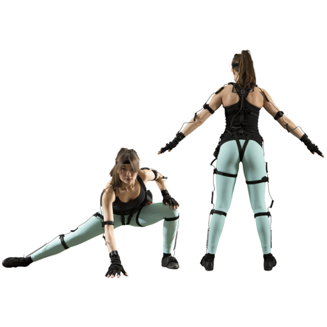
Define rigid bodies, marker geometry, attachment, tip calibration, identity and cleaning or sterilization constraints.
Explore medical-device development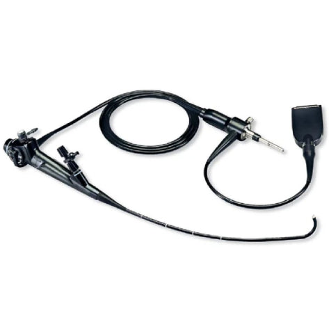
Connect navigation data to image acquisition, optical paths, camera calibration, visualization and the intended user workflow.
Explore imaging and optics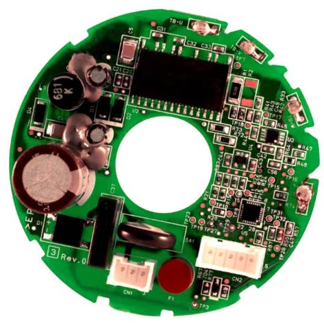
Develop measurement electronics, embedded data paths, reference artifacts and calibration methods around the required evidence.
Explore electrical engineering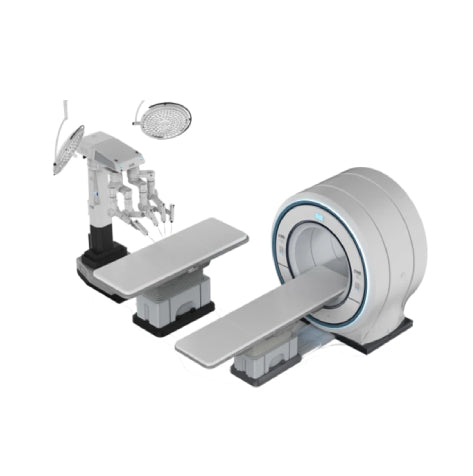
Coordinate tracking with robot frames, kinematics, motion, safety state, tools and application-level system behavior.
Explore robotics engineeringVerification planning
Methods should represent the intended geometry, workflow, environment, tool set, operating states and failure conditions closely enough to support the program's claims.
Sample needs, acceptance criteria, standards and traceability must be established for the specific device and project responsibilities.
Planning the engagement
A useful starting point includes the intended workflow, tracked objects, current imaging or device architecture, performance needs, environment and available evidence.
The system needs defined relationships among tracked instruments, a patient or anatomy reference, relevant imaging or planning data and the application view. It also needs to know when measurements, calibration and registration are valid enough for the intended workflow.
They observe motion through different physics and therefore fail differently. Optical tracking depends on visibility and camera geometry. Inertial tracking is compact and fast but accumulates drift. Mechanical systems depend on a calibrated kinematic chain. Electromagnetic systems avoid optical line of sight but can be sensitive to field distortion. The use case and failure modes should drive the choice.
Final position depends on the complete transform chain: sensor measurement, marker or tool geometry, calibration, registration, mechanical behavior, timing, filtering and application software. Any performance claim needs a defined frame, condition, method and acceptance criterion.
Yes. A focused work package can address tracking geometry, calibration, an embedded sensor path, software transforms, visualization, a test method or another difficult interface. The adjacent coordinate frames and responsibility boundaries still need to be explicit.
Calibration establishes a relationship within the device or measurement system, such as a tool tip relative to its marker body. Registration aligns one representation with another, such as patient anatomy with image data. Both produce transforms, but they answer different questions and require different evidence.
Useful inputs include the intended workflow, tracked objects, known coordinate frames, current imaging or device architecture, performance needs, operating environment, known failure cases, existing calibration methods and available test data.